

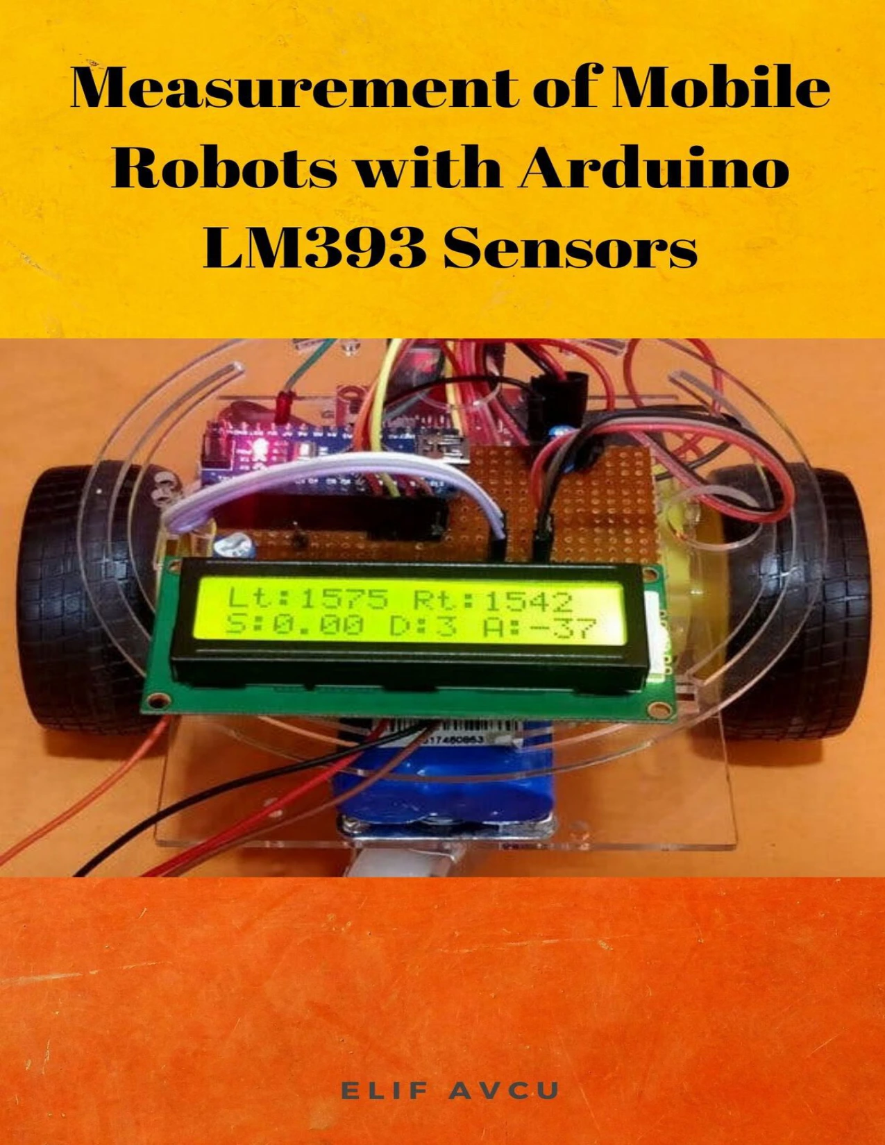
Measurement of Mobile Robots with Arduino LM393 Sensors
Original price was: $5.00.$2.50Current price is: $2.50.

Elif AVCU
Product Specs:
- File Type: PDF
- File Size: 1.1 MB
- Book Language: English
- Total Page Count: 19
- Instant Download
Build a Robot That Knows How Fast It’s Going 🤖
If you’ve ever wanted a mobile robot to report its own speed, distance travelled, and turning angle, this project guide shows you how to make it happen with an Arduino and a pair of LM393 speed sensors. The approach is practical: mount an H206 sensor module on each wheel, wire the output pins to interrupt-capable Arduino pins, and let the code calculate the numbers in real time.
Across 19 pages, the guide walks through the sensor module, the circuit, and the programming logic that turns infrared triggers into useful measurements. It’s a focused, hands-on resource for anyone comfortable with basic Arduino wiring and ready to add motion feedback to a robot.
Inside the LM393 Speed Sensor Module 📟
The heart of the measurement system is the H206 speed sensor module, which pairs an infrared light sensor with an LM393 voltage comparator. A slotted grid plate rotates with the motor shaft, and as its 20 slots pass through the sensor’s gap, the infrared beam is interrupted. Each slot produces two interrupts—one at the leading edge and one at the trailing edge—so a full wheel rotation yields 40 triggers. The comparator cleans up those triggers into a digital signal that the Arduino can count.
The guide explains how to mount the grid plate and sensor on a motor shaft that protrudes on both sides, ensuring the wheel and grid rotate together. Once that mechanical setup is correct, the sensor’s output can be used to derive speed, distance, and even the robot’s angle when two sensors are installed.
Wiring the Circuit ⚙️
The project uses an Arduino board as the controller, an L298N H-bridge motor driver to power the two DC wheels, and a joystick for manual speed and direction control. A 1602 LCD displays the measured values, while a potentiometer adjusts contrast and a resistor limits the backlight current. The whole circuit runs from a 7.4V lithium battery, with the motor driver’s onboard regulator supplying 5V to the Arduino, LCD, sensors, and joystick.
The sensor outputs are connected to external interrupt pins so that no trigger is missed while the main program runs. The guide includes a complete schematic and notes on assembling the circuit on a robot chassis.
From Interrupts to Real-World Numbers 📐
The programming section explains how to use the millis() function and interrupt service routines to measure the time between sensor triggers. From there, the guide derives RPM, linear velocity, and distance with clear formulas. For example, velocity is calculated from wheel radius and RPM, while distance is based on wheel circumference and the number of rotations counted by the sensor.
Angle measurement is handled by placing a sensor on each wheel. By comparing the rotation counts from left and right, the robot can estimate how far it has turned. The guide also addresses a common pitfall: if the robot stops, the sensor may not trigger, so the code includes a timeout that forces RPM and velocity to zero after 500 milliseconds without an interrupt.
Practical Details and Limitations
The guide is honest about the trade-offs. Because the H206 module produces 40 interrupts per rotation, the code waits for a complete wheel revolution before calculating speed. This keeps the microcontroller from being overwhelmed, but it means speed readings update once per rotation. The timeout logic solves the “stuck at last speed” problem when the robot halts.
No specialized libraries are required beyond the standard Arduino functions, and the code snippets are explained line by line. The project assumes some familiarity with basic electronics and Arduino IDE, but the instructions are detailed enough for a motivated beginner to follow.
Who This Guide Is For 🛠️
This is a good fit for:
- Arduino hobbyists who want to add speed and distance sensing to a robot
- Students working on robotics or embedded systems projects
- Makers looking for a practical introduction to interrupt-driven sensor code
- Anyone curious about how infrared speed sensors work in mobile robots
It’s not a general robotics textbook; it’s a focused project guide for a specific sensing task. If you already have a robot chassis and want reliable odometry, the material here gives you a working blueprint.
What You’ll Find Inside
- Component list and required tools
- Explanation of the LM393/H206 sensor module
- Sensor installation tips for motor shafts
- Full circuit schematic with Arduino, L298N, joystick, and LCD
- Code logic for speed, distance, and angle measurement
- Formulas for RPM, velocity, and distance
- Zero-speed detection and interrupt handling
Start Measuring Your Robot’s Motion
For competition robots and weekend builds alike, knowing how fast and how far your robot travels enables better control and navigation. This guide gives you the sensor theory, wiring, and code to make that happen with readily available parts. Download it, gather your components, and give your next robot a sense of motion.
User Reviews
Only logged in customers who have purchased this product may leave a review.
Arduino 230 Projects
Sold by Elif AVCU Original price was: $5.00.$2.50Current price is: $2.50.






There are no reviews yet.